I have altered pages from an Ikea instruction manual for the purpose of this exercise. It is important to note that most of this content does not belong to me.
Ikea instruction manuals famously use technical drawings to guide users through the assembly process without using any words. Some people love them, some hate them, and some, like me, lie somewhere in between. While I admire the design of these instruction manuals, I have often wondered if I could make certain elements clearer. To find out, I purchased “Släkt” from Ikea and took notes throughout the assembly process. Whenever the instructions confused me, I brainstormed solutions. I understand that some people may not agree with the changes I have made. These changes were made as a result of my experience.
I have included a selection of original pages from the Ikea instruction manual for "Släkt". Each problem is identified with a numbered red box. A solution to the problem is demonstrated on the following page. After figure 5, you may notice the irregular alignment of the original and altered instructions. This is because my alterations for figure 5 required me to shift the following instructions to the top of a new page. This irregular alignment continues until after figure 8, when another shift occurs.
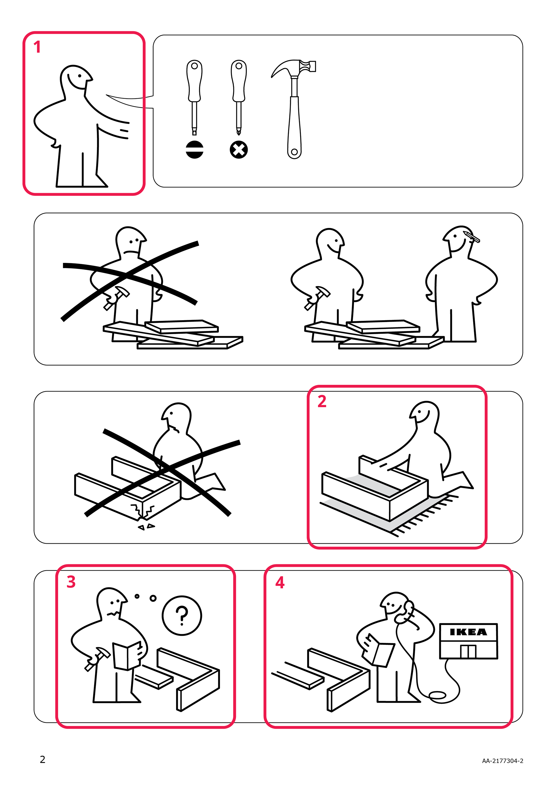
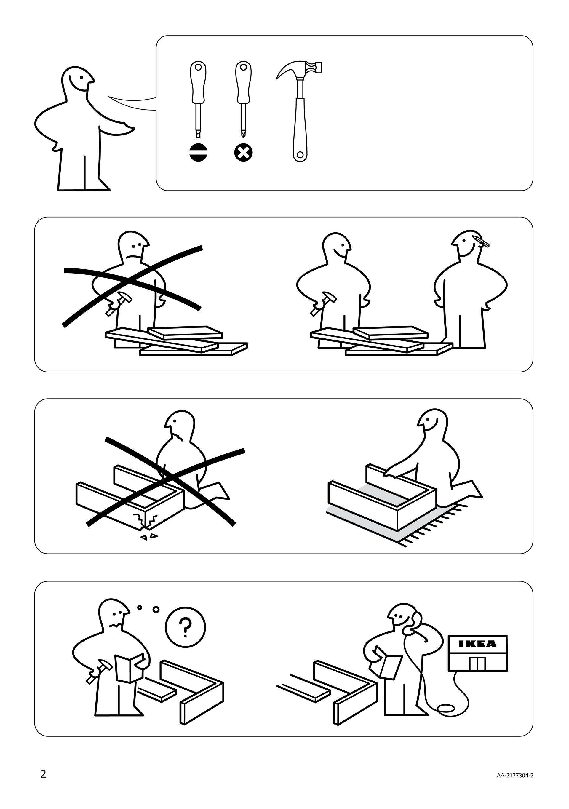
The hands of Ikea man have always bothered me. Not only are they inconsistent, they often blend in and diminish the structure of the objects he is touching. The inconsistency is apparent when examining Ikea man's hands in figures 1 and 3. The merging of hands with objects is demonstrated in figures 2, 3, and 4. Further inconsistency is visible in figure 4, where one hand is separated from an object and the other is fused to an object. To fix these issues, I gave Ikea man a new uniform hand style that clearly separates him from objects.
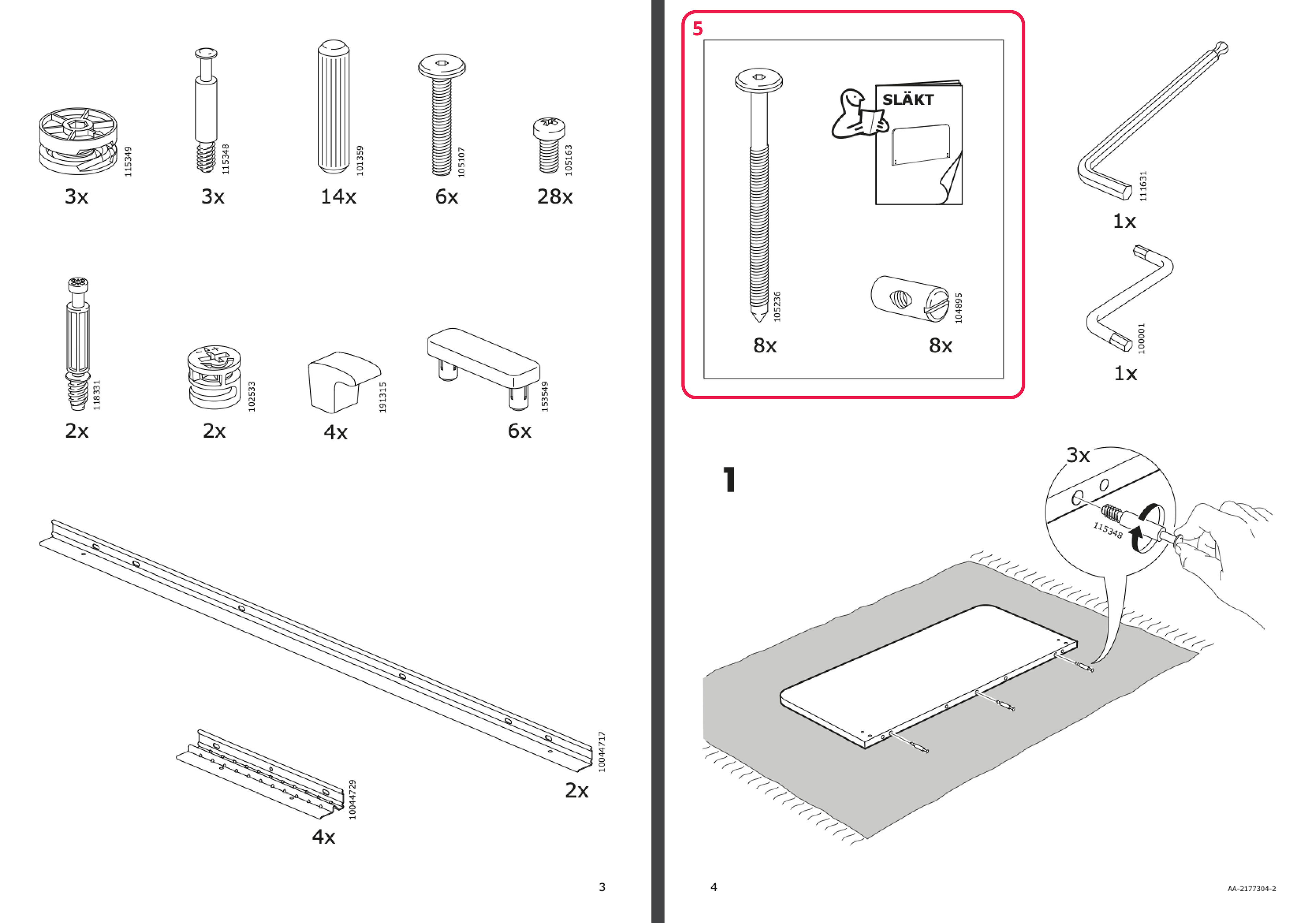
Before beginning the assembly process, I tried to determine what figure 5 was trying to express. I thought this might be an indication that parts #105236 and #104895 were located in another box. After closer examination, the image appears to feature an additional instruction manual for a specific part. This is misleading, as no such instruction manual exists. As I suspected originally, this illustration indicates that parts #105236 and #104895 are located in another box. This illustration caused a lot of unnecessary confusion.
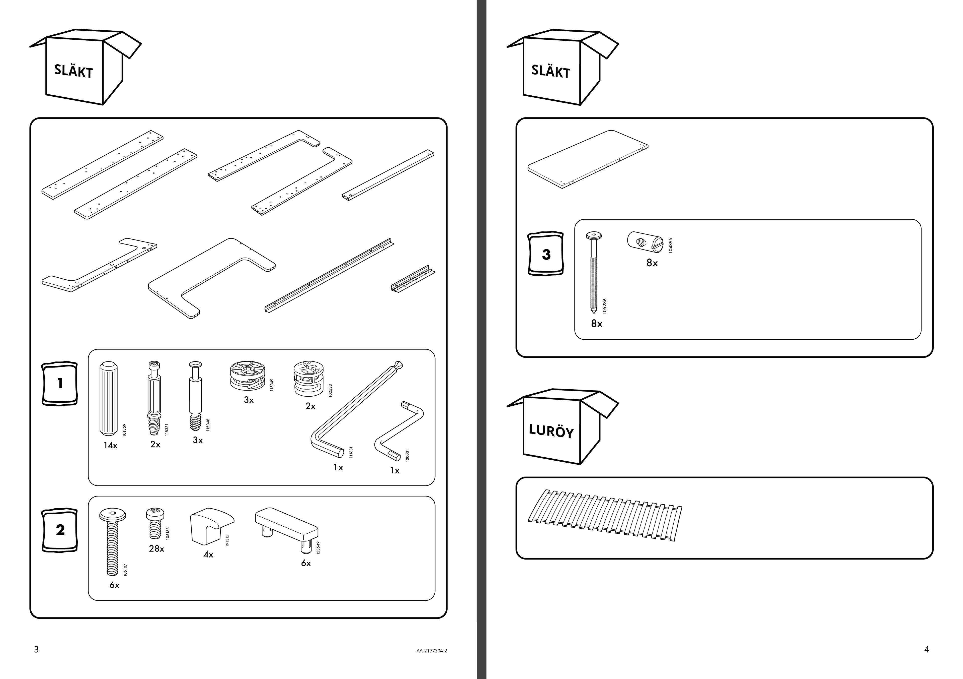
Ikea chooses to list their hardware and exclude other building materials. This means the record of items needed for assembly is incomplete. While opening the packages needed for this product, I noted that this entire system was lacking organization. I had to open all three packages before beginning, taking up valuable floor space, because it wasn't clear which package contained the items I needed first.
My solution for these issues is to include all parts needed for this product, categorized by which box or bag they are in. This clearly communicates what the user can expect to find and where they can expect to find it.
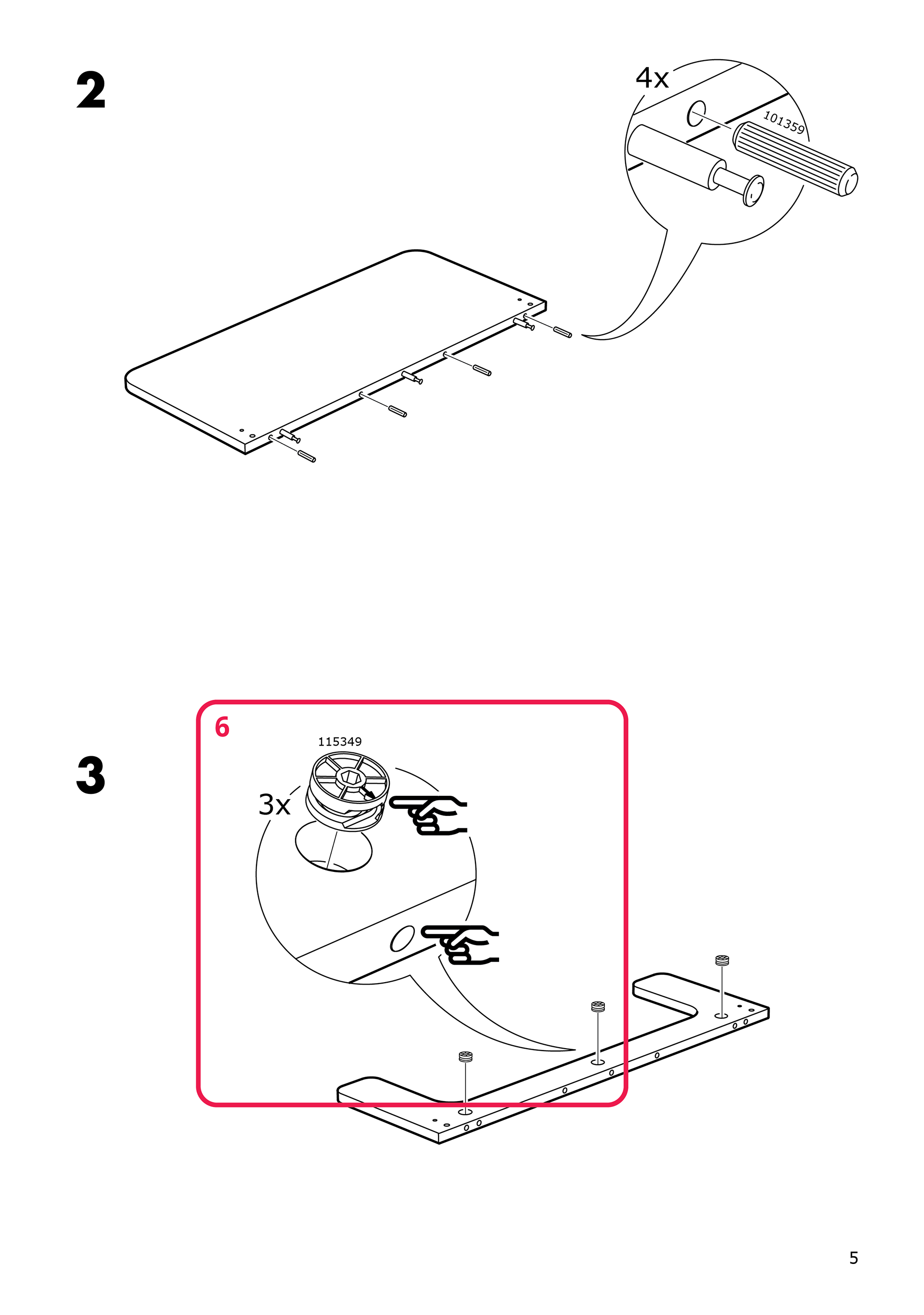

Figure 6 illustrates a hand pointing to a small arrow on part #115349 and another hand pointing to a hole. The directions are unclear because the arrow is so small and easily missed. To resolve this issue, I suggest adding a second image to demonstrate correct installation of part #115349. Including an additional arrow in this image helps to indicate proper alignment of part #11549 with the hole.
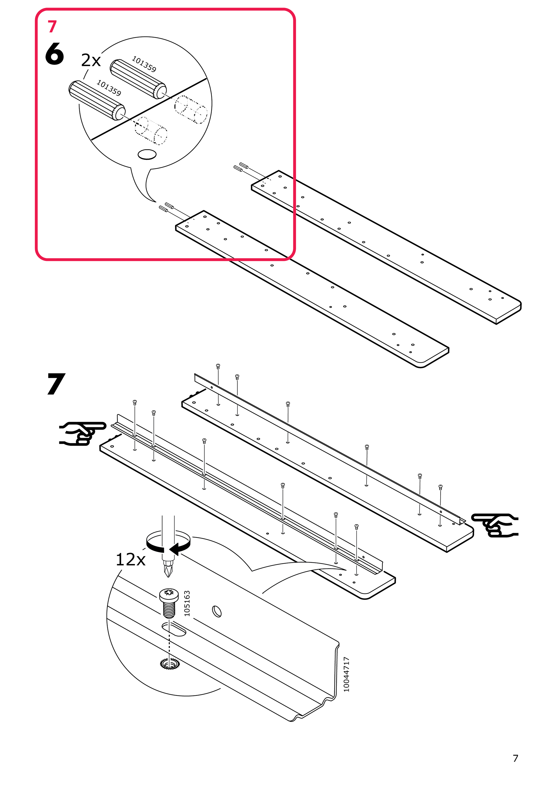
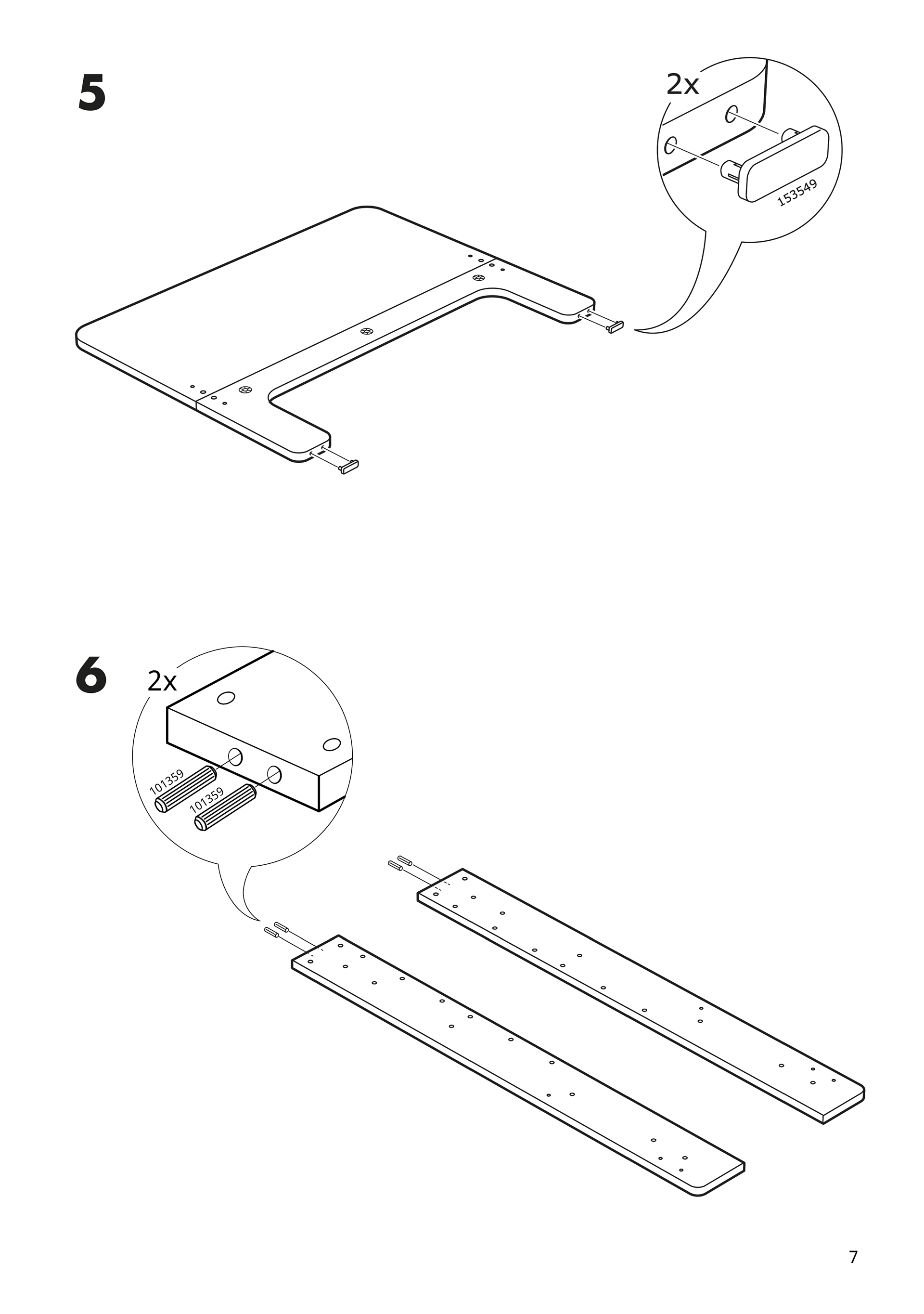
Figure 7 demonstrates the installation of part #101359. I questioned why this illustration was made from this perspective. While it matches the perspective of the rest of the drawing, it unnecessarily complicates the image, which some users might find confusing. To fix this issue, I propose changing the perspective of the drawing.
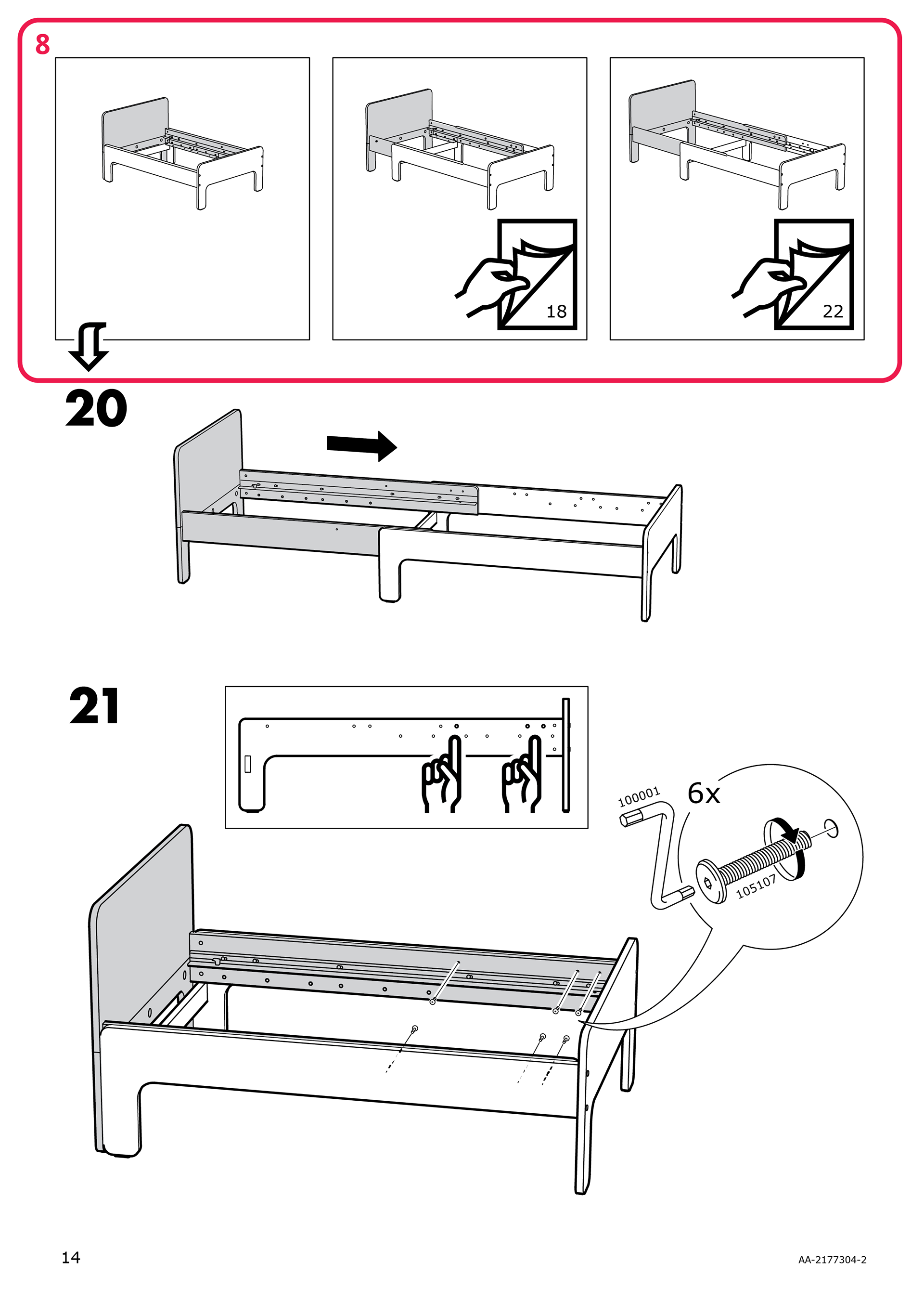
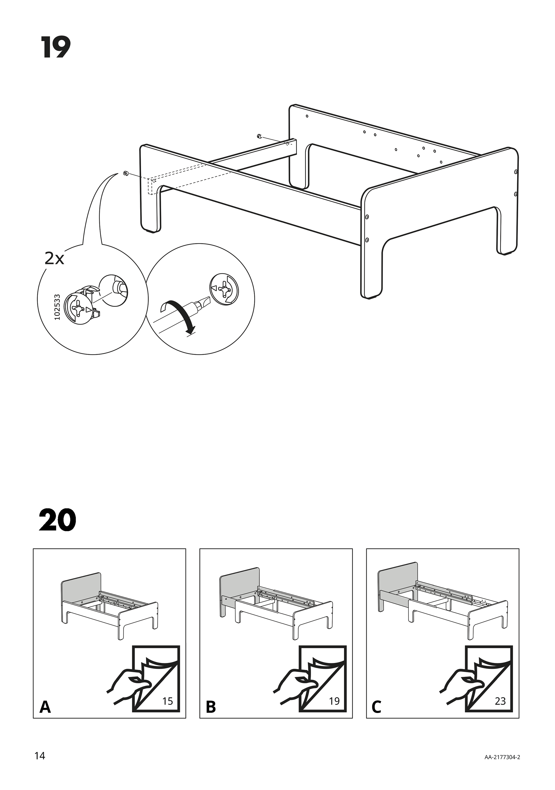
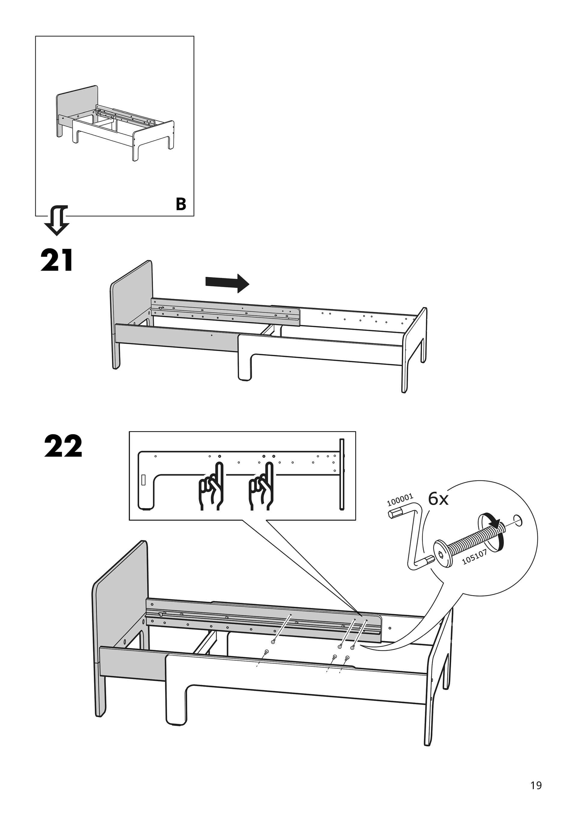
Figure 8 indicates a crucial decision being made by the user—they must choose which version of the product they are assembling. The problem here is that the eyes of the user may be drawn to the number of the next step, overlooking this direction entirely. In fact, this is exactly what happened to me. I completed the assembly process and realized that I had accidentally chosen the wrong version of the product. This meant I had to partially disassemble and reassemble the parts to complete the intended version. This could have been avoided if more importance was communicated through figure 8. For this reason, my suggestion would be to give this instruction a step number. This draws more attention, forcing the user to acknowledge this crucial stage of the assembly process. Labeling each product version with "A", "B", or "C" further emphasizes that the user must make a choice between one of the options.
With reference to my alteration of figure 8, adding an extra step means that step 20 now becomes step 21. After separating these steps, it is important to include an illustration of option "A" at the beginning of the option "A" assembly process.
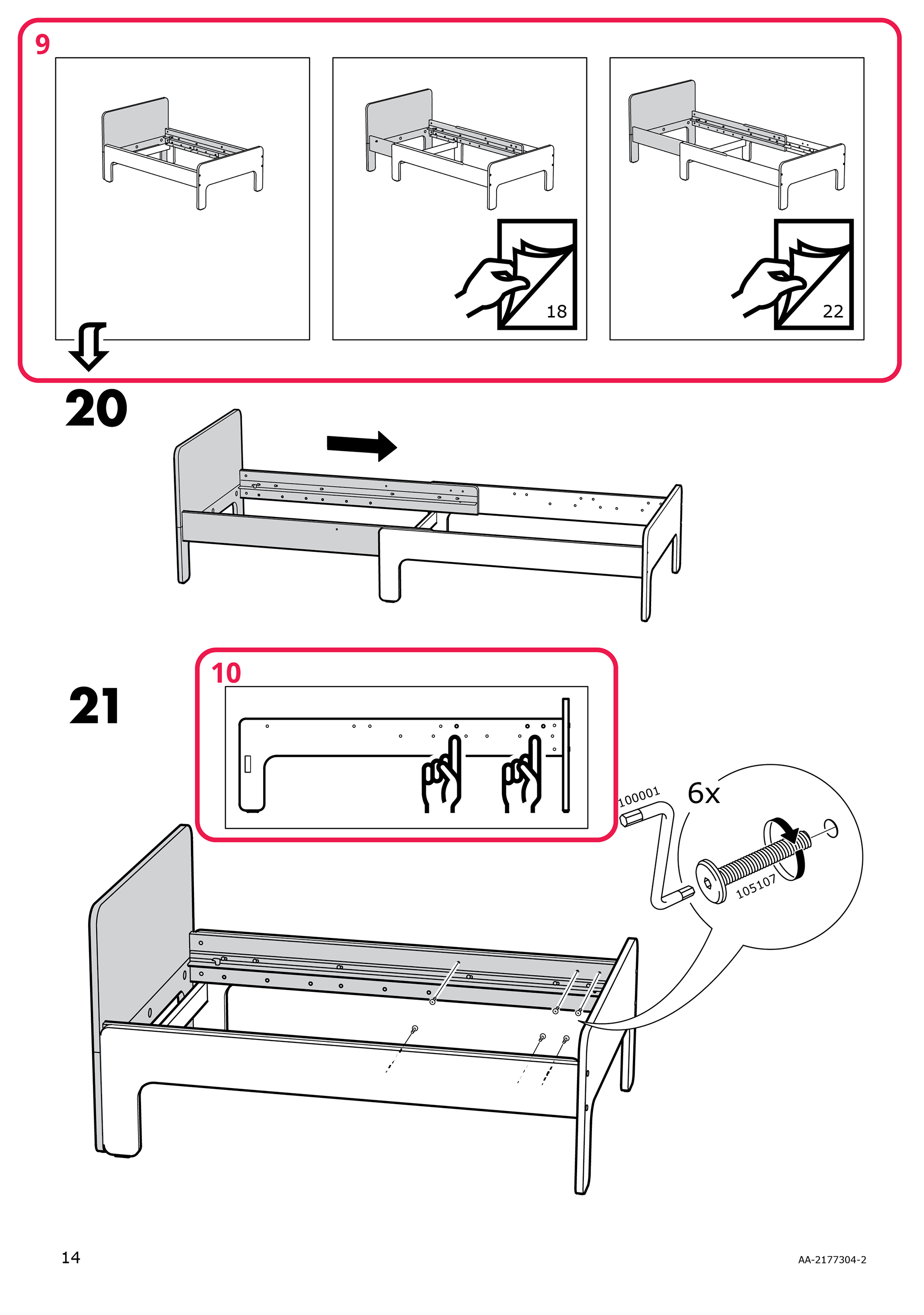
The user may be faced with another problem when they progress to the next step. Much like the issue discussed with figure 8, figure 10 may be overlooked, as it does not communicate importance or association with the illustration below. During the assembly process, I overlooked figure 10. This does not seem like a serious issue until closer inspection. Figure 10 contains hands pointing to three holes to the left of another hole. This hole is not visible in the image below, which lead me to installing part #105107 in the wrong place. My solution for this problem is to connect these two illustrations, reducing the likelihood that figure 10 is overlooked.
The user may be faced with another problem when they progress to the next step. Much like the issue discussed with figure 8, figure 10 may be overlooked, as it does not communicate importance or association with the illustration below. During the assembly process, I overlooked figure 10. This does not seem like a serious issue until closer inspection. Figure 10 contains hands pointing to three holes to the left of another hole. This hole is not visible in the image below, which lead me to installing part #105107 in the wrong place. My solution for this problem is to connect these two illustrations, reducing the likelihood that figure 10 is overlooked.
As a result of my alteration of figure 8, the user should have no issue finding the page number associated with the product version they choose. The second image in figure 11 is already shown in my alteration of figure 8—there is no need to repeat it. My solution is to label the product version with "B", as this clarifies which product version the following instructions refer to.
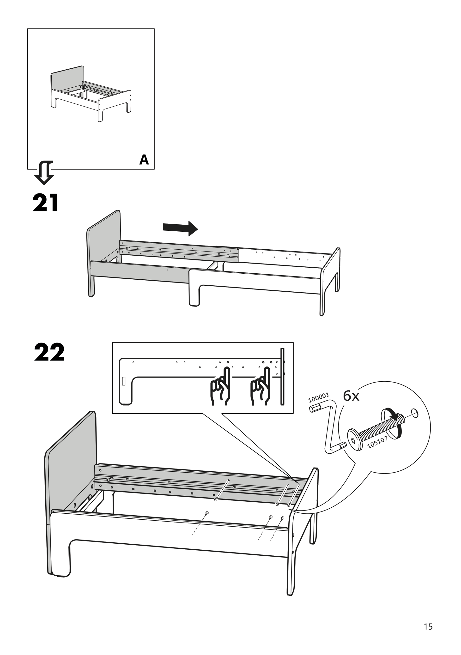
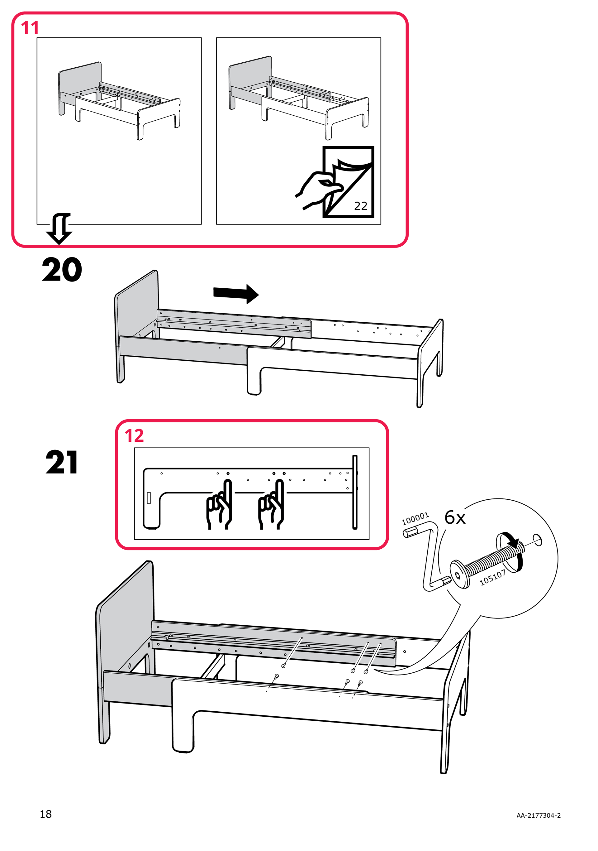
With reference to my alteration of figure 10, it is possible that figure 12 may be overlooked. My solution is to connect the image in figure 12 with the image below figure 12.
With reference to my alteration of figure 10, it is possible that figure 12 may be overlooked. My solution is to connect the image in figure 12 with the image below figure 12.
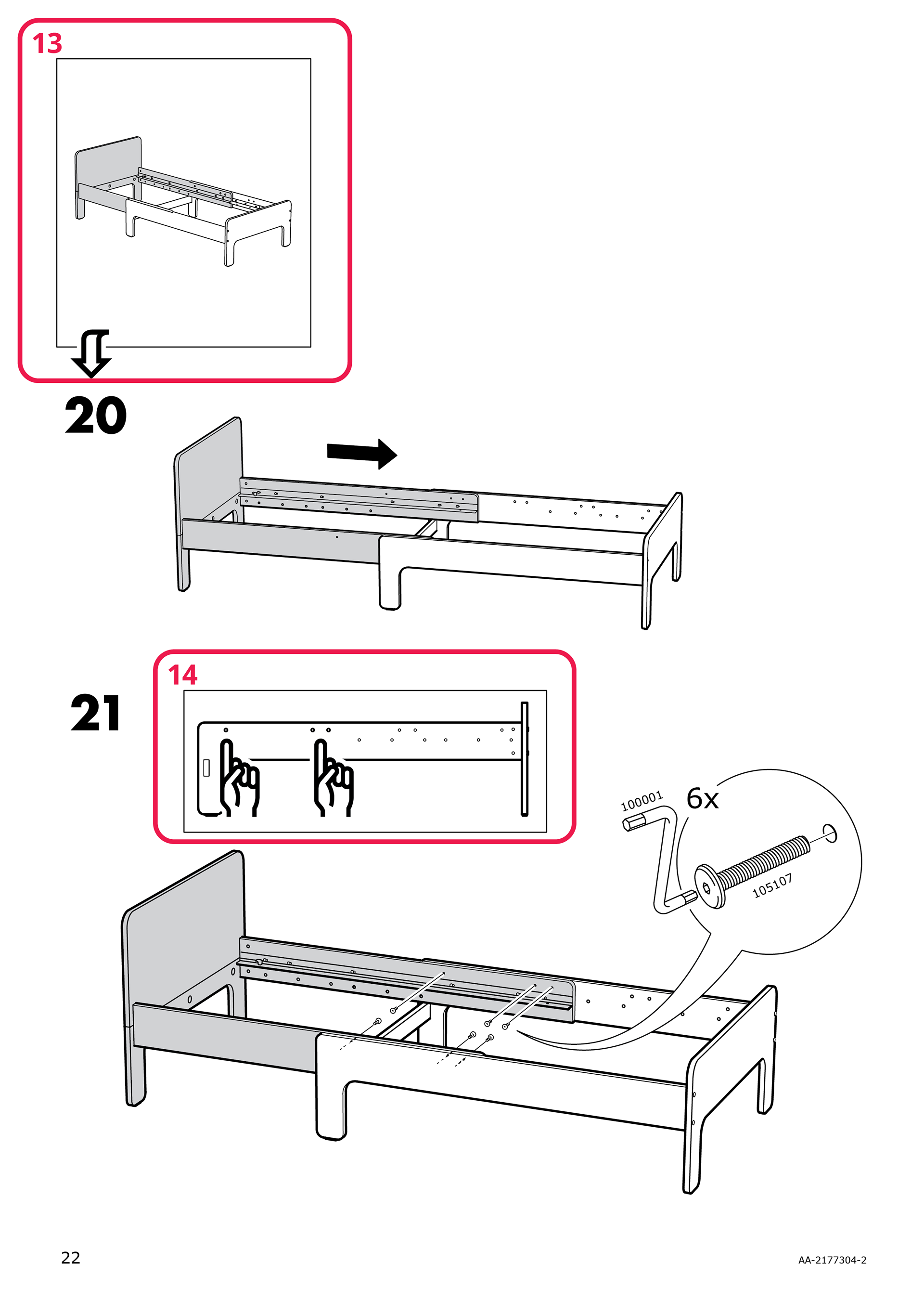
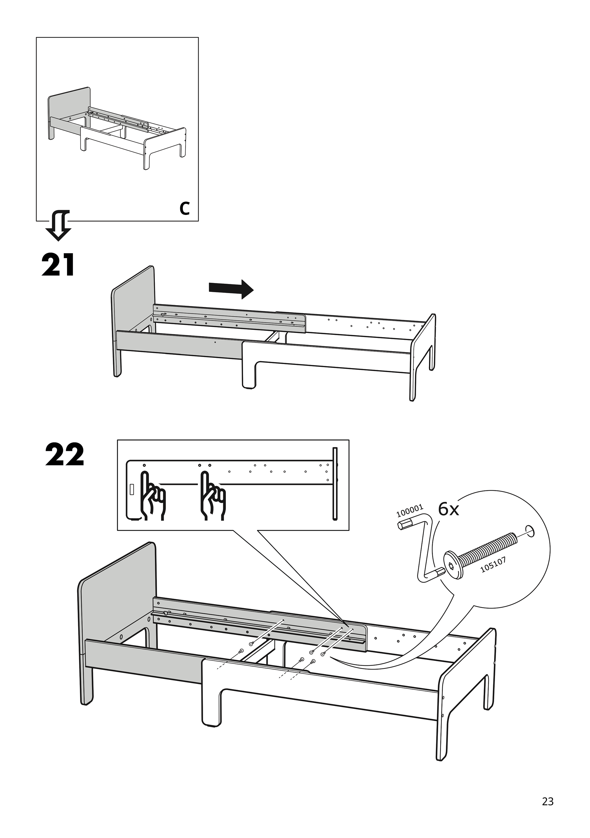
For consistency and to clarify which product version the instructions following figure 13 are referring to, I would recommend labelling the image with "C".
With reference to my alteration of figure 10, it is possible that figure 14 may be overlooked. My solution is to connect the image in figure 14 with the image below figure 14.
With reference to my alteration of figure 10, it is possible that figure 14 may be overlooked. My solution is to connect the image in figure 14 with the image below figure 14.